QUARTERPIPE FRAME
Building the frame for a quarterpipe
The first picture shows an 8ft (2440mm) quarterpipe frame, next to its deck frame. You will note the two ends of the frame are braced with a diagonal angle iron, which carries the main centre crossrail. This qurterpipe is designed to have a "drop" of 9 inches, the drop being the amount a curved ramp is lower in the centre than a flatbank between the same top and bottom points. If you want a steeper ramp, shorten this diagonal so it sits lower in the end frames.
Make sure that the 50mm flat toprail is bolted to the deck frame, with the nuts on the deck side. Weld the bolts to the flat. Once that ramp is surfaced, you can't get at these bolts.
Once the two end frames are built, with a centre frame for extra bracing, weld them first to the 50mm flat bar rail that was drilled when building the deck frame, and build the ramp whilst it is bolted to the deck frame. This will mean that it will all fit, because you have built them fitted.
Think again here whether the ends will need to be clad with 18mm ply, because the frame will have to be that much narrower so that the 2440mm decking panels overlap the ends as required by 18mm.
;NEW : CHECK OUT "ENGINEERING UPDATE PAGE"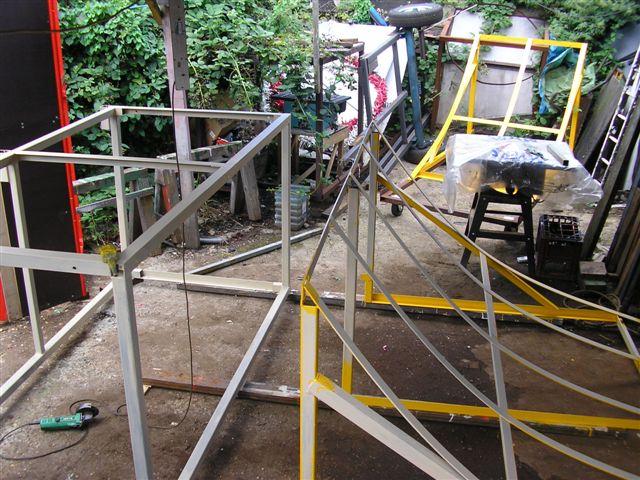
Building the end of the frame

Keep referring to the pictures and sketches. Not having a flat yard to work on, I find it simpler when building to work on two 10ft lengths of 100x50 box tacked under the end of the deck frame. These protrude from the front of the frame and give me an accurate base to build the quarter.
Take the 68" angles that will be the base, and drill a 13mm hole about 1ft (300mm) from the deck end. This will eventually be a mounting hole for bolting the the park.
Then weld a 50mm offcut of 50mm angle onto the end, as shown in the sketch above, This will provide a sound square surface to weld the box section upright to. Weld the 43" 50mm box at an exact right angle to the base angle. Then weld a 50mm length of 25mm flat to the top of the box, extending the "backwall" of the box. Then weld in the diagonal braces. These must be accurate, and they must be exactly level with each other., because the curve of the ramp depends on them.
You should already have the 50mm flat rail bolted to the front of the previously constructed deck frame. Clamp the two end frames to the uprights of the deck frame, with the 25mm flats butting up to the 50mm crossrail, and weld them in place. Fit the centre brace in the same way. REMEMBER, the diagonal and base angleirons must face INWARDS, so work out each end carefully before welding them together.
You can make the centre brace with the diagonal as well, but it decreases the flexibility of the pipe, and means you will have to split your cross braces in tow pieces, which increases the possibility of minute errors throwing the curve out of line.
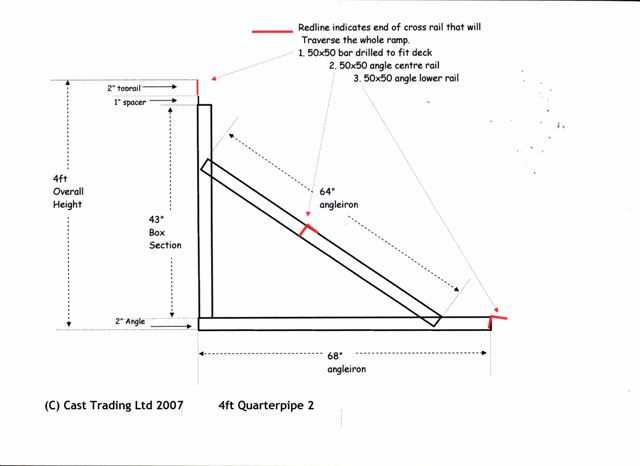
The top rail, the 50mm flat that is bolted to the deck frame, is already welded in place. Tak egreat care now getting the two ends perfectly square with respect to the deckframe and each other, before fitting the lower rail.
Next cut a length of angle for the lower rail. This needs to be the full widthe of the ramp, less 3mm at each end so it snugs inside the base angleirons. You will just have to touch the corners off so they fit the slight inner curve at the joint of the angleiron. Tack them lightly in position at the bottom of the web where it touches the bottom web of the base angle. You will see from the sketch that this needs to be angled forward. You may need to adjust the angle when you try-fit the ramp formers.
Once the above is done, and checked again for square, cut a length of angle for the centre rail. This will need to be the full width less twice the angle iron, so that it fits flush between the two end diagonals.
Now try one length of 50mm flat, tacked to the top rail, and clamped into the centre and lower rails. Use this to twist the lower rail so that the flat fits flush to it. Take the flat off and finish off all the tacks.
Building the curve
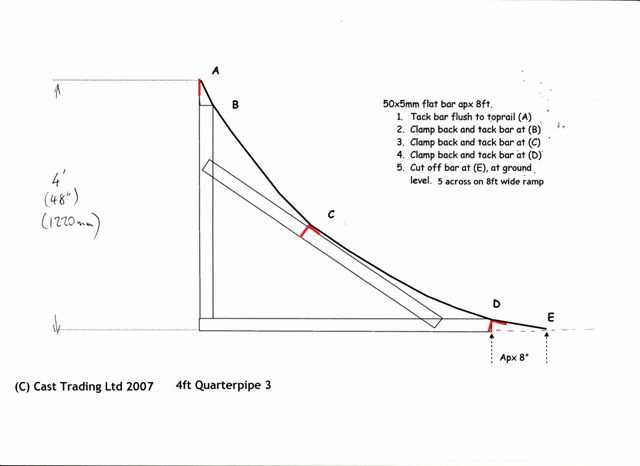
Now that the main frame is built, cut your 5 flats for the ramp formers. One by one, doing the outer two first. I normally measure one length roughly, and tack it in place to get an accurate length, before cutting off the end that will touch the ground. When one is measured, cut the others to the same length.
Tack them to the toprail, just a couple of mm lower than the top edge, so that the weld doesn't protrude above the toprail.Check that the far end of the flat is square on the lower rail. Pull the flat down with a clamp so that you can tack it to the top of the box section upright. It may help here if you have already loosely clamped the flat to the centre crossrail. Weld the flat to the box, and then finish the weld to the toprail.
Making sure that the flat has curved, and not bent, tighten the clamp on the centre rail. As you tighten the clamp, exert pressure on the flat between top and centre to help it curve, so that as you clamp it, it is lying flat on the centre angle. Check again that the flat is square on the lower rail, then weld the centre completely.
Check again that the flat is square on the lower rail, clamp that flush, and weld.
Check back over all welds to ensure you haven't left any just tacked. Prime and Paint.
Fitting the rolling surface.
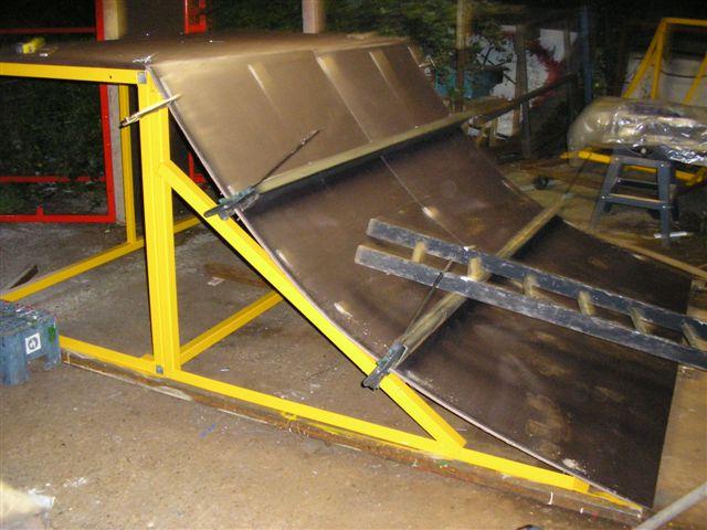
The basic cladding on the curve is two sheets of ordinary ply running up and down as shown, then two ordinary sheets crosswise, and then the top phenolic surfecd sheets again up and down.
Cut the first two sheets 1/2 inch, (13mm) longer than the curved flats. Clamp them loosly flush at the top with the coping rail. Clamp them tight, and make sure there is no gap in the centre, and that they are sqaure all round. Drill and screw with the absolute minimum of screws needed to hold them in place.
Put your first crosswise sheet again flush with the coping rail, and cut the lower sheet so that it iextends over the first sheet at the botton by about an inch (25mm). Screw both down again with the bare minimum of screws.
Then the same again with the top surface sheets, again cut about an inch longer that the sheet beneath. Get both sheets snug together, clamped down, and flush with the coping rail, and put a line of screws across the top where the flat curve formers are.
Put a couple of screws on the either side of the centre joint, to keep the sheets together, and then begin screwing each sheet down the centre line, about every 9inches, but try and avoid your cross braces, or where the metal is doubled. Once the centres are done, do all the outer edges of each sheet, again working downwards.
The reason we allow each layer to overlap the previous, is so the flat bar and the ply form a wedge shape. If they were all cut to the same length you would end up with a 23mm step at the bottom of the ramp.
It may help to clamp bars right across as in the photo, it really helps in keeipng the sheets flat and square.
You will also find that using a short ladder as in the picture, hooked over the coping rail is most useful, as you will find that when you climb the ramp and start drilling, you slide back down!
Sample Photo 5

Sample Photo 6